DEMONTAGE
MESURE DE PRECAUTION / REMARQUE / CONSEIL
CONSEIL:
MESURE DE PRECAUTION / REMARQUE / CONSEIL
PIECES CONSTITUTIVES (DEMONTAGE)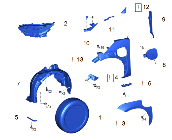
|
Procédure | N° de référence |
.png) |
.png) |
 |
|---|---|---|---|---|---|
|
1 | ENSEMBLE DE ROUE |
- | - |
- | - |
|
2 | ENSEMBLE DE PHARE |
- | - |
- | - |
|
3 | SOUS-ENSEMBLE DE MOULURE D'AILE AVANT |
75602A |
|
- | - |
|
4 | DISPOSITIF DE RETENUE LATERAL DE PARE-CHOCS AVANT |
52536 |
|
- | - |
|
5 | BOUCLIER ANTI-ECLABOUSSURES D'AILE AVANT |
53896B | - |
- | - |
|
6 | SOUS-ENSEMBLE DE GARDE-BOUE DE PANNEAU D'AILE |
76902B |
|
- | - |
|
7 | DOUBLURE D'AILE AVANT |
53876A | - |
- | - |
|
8 | ENSEMBLE DE BOITIER D'ENTREE DE CHARGE |
773B0 | - |
- | - |
|
9 | JOINT D'AILE AVANT |
53883B | - |
- | - |
|
10 | JOINT ENTRE CAPOT ET AILE AVANT |
53389B | - |
- | - |
|
11 | JOINT LATERAL ENTRE L'AILE AVANT ET L'AUVENT |
53867H | - |
- | - |
|
12 | SOUS-ENSEMBLE DE CACHE SUPERIEUR DE MONTANT AVANT |
60118 |
|
- | - |
|
13 | PANNEAU D'AILE AVANT |
53812C |
|
- | - |
|
*a | Pour côté gauche |
- | - |
PROCÉDURE
1. DEPOSER L'ENSEMBLE DE ROUE
Cliquer ici
.gif)
2. DEPOSER L'ENSEMBLE DE PHARE
Cliquer ici
Cliquer ici
3. DEPOSER LE SOUS-ENSEMBLE DE MOULURE D'AILE AVANT
|
|
Cliquer ici |
4. DEPOSER LE DISPOSITIF DE RETENUE LATERAL DE PARE-CHOCS AVANT
|
|
Cliquer ici |
5. DEPOSER LE BOUCLIER ANTI-ECLABOUSSURES D'AILE AVANT
Cliquer ici
6. DEPOSER LE SOUS-ENSEMBLE DE GARDE-BOUE DE PANNEAU D'AILE
|
|
Cliquer ici |
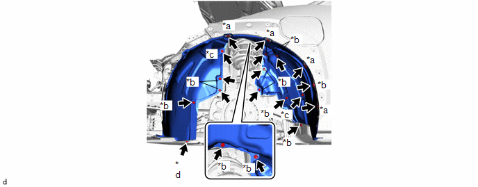
7. DEPOSER LA DOUBLURE D'AILE AVANT
|
*a | Oeillet |
*b | Agrafe |
|
*c | Vis et œillet |
* d | Vis |
8. DEPOSER L'ENSEMBLE DE BOITIER D'ENTREE DE CHARGE (pour côté gauche)
Cliquer ici
9. DEPOSER LE JOINT D'AILE AVANT

10. DEPOSER LE JOINT ENTRE CAPOT ET AILE AVANT
Cliquer ici
11. DEPOSER LE JOINT LATERAL ENTRE L'AILE AVANT ET L'AUVENT
Cliquer ici
12. DEPOSER LE SOUS-ENSEMBLE DE CACHE SUPERIEUR DE MONTANT AVANT
|
|
Cliquer ici |
13. DEPOSER LE PANNEAU D'AILE AVANT
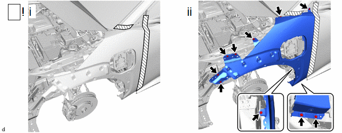
(1) Appliquer du ruban adhésif de protection autour du panneau d'aile avant, comme indiqué sur le schéma.
(2) Déposer les 10 boulons et le panneau d'aile avant.
 Aile Avant
 Remontage
Les modes recyclage d'air/air extérieur ne changent pas de position
DESCRIPTION Si le mode d'entrée d'air ne peut pas être basculé entre l'air extérieur/recyclage d'air ou si des odeurs de gaz d'échappement sont perceptibles en dépit de la sélection du mode de recyclage d'air, les facteurs suivants peuvent être à l'origine du problème.
Symptôme F ...
Comment Proceder A La Recherche De Pannes
MESURE DE PRECAUTION / REMARQUE / CONSEIL MESURES DE PRECAUTION A SUIVRE LORS DE LA RECHERCHE DE PANNES
REMARQUE:
Etant donné que l'ordre de diagnostic est important pour permettre un bon diagnostic, veiller à procéder à la recherche de pannes en utilisant la section "Comment utiliser la r ...
Message de capteur à ultrasons (angle avant gauche) manquant
DESCRIPTION
Ce DTC est émis lorsqu'une coupure ou un court-circuit se produit dans la ligne de communication entre un capteur à ultrasons d'angle avant (capteur FL) et le capteur à ultrasons central avant (capteur FL), ou en cas de dysfonctionnement d'un capteur à ultras ...