


POSE
MESURE DE PRECAUTION / REMARQUE / CONSEIL
CONSEIL:
MESURE DE PRECAUTION / REMARQUE / CONSEIL
PIECES CONSTITUTIVES (REPOSE)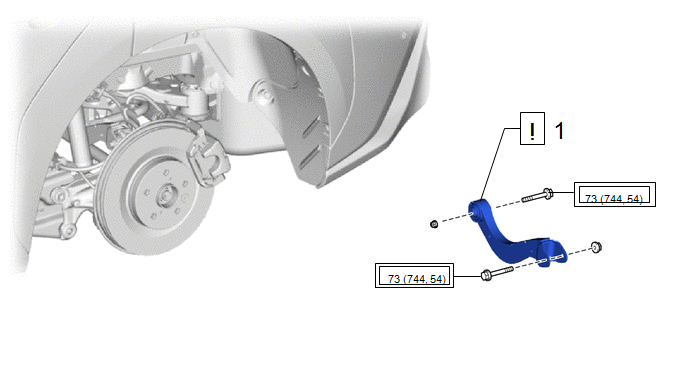
|
Procédure | N° de référence |
.png) |
.png) |
 |
|---|---|---|---|---|---|
|
1 | ENSEMBLE DE BRAS DE COMMANDE SUPERIEUR ARRIERE |
48790 |
|
- | - |
.png) |
Couple de serrage pour "Les principaux domaines impliquant les performances de base du véhicule, tels que le déplacement/le virage/l'arrêt" : N*m (kgf*cm, lbf*pi) |
- | - |
|
Procédure | N° de référence |
|
|
| |
|---|---|---|---|---|---|
|
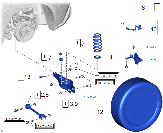
2 | REPOSER PROVISOIREMENT L'ENSEMBLE DE BRAS DE SUSPENSION ARRIERE N° 1 |
48720A |
|
- | - |
|
3 | REPOSER PROVISOIREMENT L'ENSEMBLE DE BRAS DE SUSPENSION ARRIERE N° 2 |
48740F |
|
- | - |
|
4 | COUSSINET INFERIEUR DE RESSORT HELICOIDAL ARRIERE |
48258C | - |
- | - |
|
5 | RESSORT HELICOIDAL ARRIERE |
48231B |
|
- | - |
|
6 | STABILISER LA SUSPENSION |
- |
|
- | - |
|
7 | ENSEMBLE DE BIELLETTE DE BARRE STABILISATRICE ARRIERE |
48840A |
|
- | - |
|
8 | REPOSER L'ENSEMBLE DE BRAS DE SUSPENSION ARRIERE N° 1 |
48720A |
|
- | - |
|
9 | REPOSER L'ENSEMBLE DE BRAS DE SUSPENSION ARRIERE N° 2 |
48740F |
|
- | - |
|
10 | SOUS-ENSEMBLE DE CAPTEUR DE COMMANDE DE HAUTEUR ARRIERE GAUCHE |
89408C | - |
- | - |
|
11 | COUVERCLE DE BRAS DE COMMANDE INFERIEUR N° 2 |
48738C | - |
- | - |
|
12 | ROUE ARRIERE |
- | - |
- | - |
|
13 | SOUS-ENSEMBLE DE CAME DE REGLAGE DE PINCEMENT DE SUSPENSION ARRIERE |
48409 |
|
- | - |
|
*a | Pour côté gauche avec capteur de commande de hauteur |
- | - |
|
*1 | CAME DE REGLAGE DE CARROSSAGE N° 2 |
- | - |
|
|
Couple de serrage pour "Les principaux domaines impliquant les performances de base du véhicule, tels que le déplacement/le virage/l'arrêt": N*m (kgf*cm, lbf*pi) |
.png) |
N*m (kgf*cm, lbf*pi): couple prescrit |
|
Procédure | N° de référence |
|
|
| |
|---|---|---|---|---|---|
|
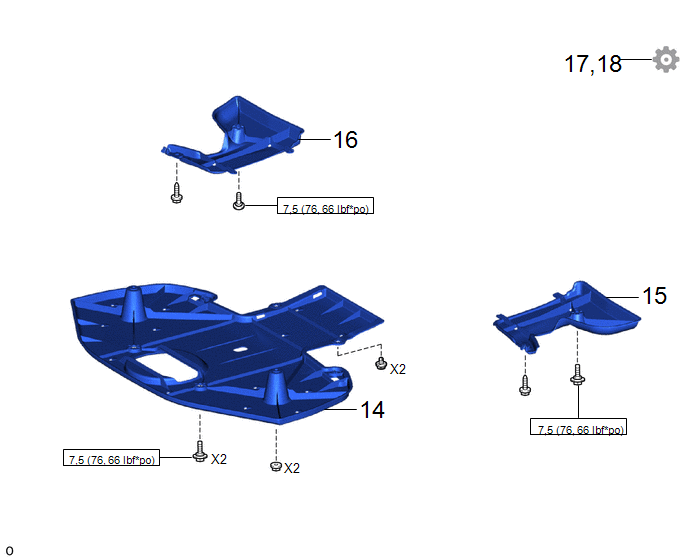
14 | CACHE DE RENFORT DE SUSPENSION ARRIERE |
53661B | - |
- | - |
|
1,5 | PROTECTION DE SUPPORT DE DIFFERENTIEL N° 2 |
52384C | - |
- | - |
|
16 | PROTECTION N° 1 DE SUPPORT DE DIFFERENTIEL |
52383E | - |
- | - |
|
17 | VERIFIER ET REGLER LA GEOMETRIE DES ROUES ARRIERE |
- | - |
- |
|
|
18 | EFFECTUER L'INITIALISATION |
- | - |
- |
|
|
|
N*m (kgf*cm, lbf*pi): couple prescrit |
- | - |
PROCÉDURE
1. REPOSER L'ENSEMBLE DE BRAS DE COMMANDE SUPERIEUR ARRIERE
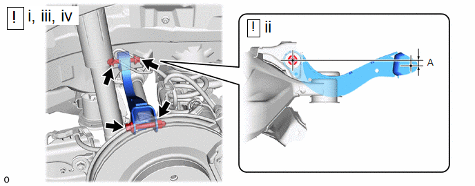
(1) Reposer provisoirement l'ensemble de bras de commande supérieur arrière sur le sous-ensemble de traverse de suspension arrière à l'aide du boulon et de l'écrou.
REMARQUE:
Ne pas tourner l'écrou car celui-ci est muni d'une butée. Serrer le boulon en bloquant l'écrou.
(2) Placer l'ensemble de bras de commande supérieur arrière comme indiqué sur le schéma.
Longueur de référence (A):
12.5 mm (1.209 in.)
(3) Reposer provisoirement l'ensemble de bras de commande supérieur arrière sur le sous-ensemble de porte-essieu arrière à l'aide du boulon et de l'écrou.
REMARQUE:
(4) Serrer complètement les 2 boulons.
Torque:
73 N·m {744 kgf·cm, 54 ft·lbf}
REMARQUE:
Ne pas tourner l'écrou car celui-ci est muni d'une butée. Serrer le boulon en bloquant l'écrou.
2. REPOSER PROVISOIREMENT L'ENSEMBLE DE BRAS DE SUSPENSION ARRIERE N° 1
|
|
Cliquer ici |
3. REPOSER PROVISOIREMENT L'ENSEMBLE DE BRAS DE SUSPENSION ARRIERE N° 2
|
|
Cliquer ici |
4. REPOSER LE COUSSINET INFERIEUR DE RESSORT HELICOIDAL ARRIERE
Cliquer ici
.gif)
5. REPOSER LE RESSORT HELICOIDAL ARRIERE
|
|
Cliquer ici |
6. STABILISER LA SUSPENSION
|
|
Cliquer ici |
7. BRANCHER L'ENSEMBLE DE BIELLETTE DE BARRE STABILISATRICE ARRIERE
|
|
Cliquer ici |
8. REPOSER L'ENSEMBLE DE BRAS DE SUSPENSION ARRIERE N° 1
|
|
Cliquer ici |
9. REPOSER L'ENSEMBLE DE BRAS DE SUSPENSION ARRIERE N° 2
|
|
Cliquer ici |
10. REPOSER LE SOUS-ENSEMBLE DE CAPTEUR DE COMMANDE DE HAUTEUR ARRIERE GAUCHE (pour côté gauche avec capteur de commande de hauteur)
Cliquer ici
11. REPOSER LE BRAS DE COMMANDE INFERIEUR N° 2
Cliquer ici
12. REPOSER LA ROUE ARRIERE
Cliquer ici
13. REPOSER LE SOUS-ENSEMBLE DE CAME DE REGLAGE DE PINCEMENT DE SUSPENSION ARRIERE
|
|
Cliquer ici |
14. REPOSER LE CACHE DE RENFORT DE SUSPENSION ARRIERE
Cliquer ici
15. REPOSER LA PROTECTION DE SUPPORT DE DIFFERENTIEL N° 2
Cliquer ici
16. REPOSER LA PROTECTION DU SUPPORT DE DIFFERENTIEL N° 1
Cliquer ici
17. VERIFIER ET REGLER LA GEOMETRIE DES ROUES ARRIERE
Cliquer ici
18. EFFECTUER L'INITIALISATION
|
Avance du stationnement (avec stationnement avancé) |
|
|
Système de moniteur de vision panoramique |
|
|
Système d'éclairage (EXT) |
|
 Depose
Emplacement Des Pieces
EMPLACEMENT DES PIECES SCHEMA
*1 ENSEMBLE D'ACTIONNEUR DE FREIN
- ECU DE CONTROLE DE DERAPAGE N°2
- - SCHEMA
*1 ECU DE COMMANDE EV
*2 ENSEMBLE DE COMBINE D'INSTRUMENTS
- TEMOIN DE RAPPEL DE CEINTURE DE SECURITE - TEMOIN DE RAPPEL DE CEINTUR ...
Circuit à haute tension du moteur électrique
DESCRIPTION La cause du dysfonctionnement peut être le circuit à haute tension du moteur électrique.
Vérifier la résistance interne du moteur électrique et l'état de branchement de la ligne à haute tension entre l'inverseur et le moteur électrique pour vérifier s'il y a une coupure ou un ...
Pose
POSE MESURE DE PRECAUTION / REMARQUE / CONSEIL PIECES CONSTITUTIVES (REPOSE)
Procédure N° de référence
1 SERVICE PLUG (PRISE DE SERVICE)
G3834
- -
2 SOUS-ENSEMBLE DE PANNEAU D'EXTREMITE ARRIERE DE CONSOLE
- -
- ...