DEMONTAGE
MESURE DE PRECAUTION / REMARQUE / CONSEIL
PIECES CONSTITUTIVES (DEMONTAGE)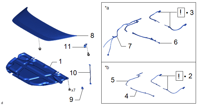
|
ProcÃĐdure | N° de rÃĐfÃĐrence |
.png) |
.png) |
 |
|---|---|---|---|---|---|
|
1 | ISOLANT DE CAPOT |
53341B | - |
- | - |
|
2 | SOUS-ENSEMBLE DE GICLEUR DE LAVE-GLACE |
85035 |
|
- | - |
|
3 | DEPOSER L'ENSEMBLE DE DURITE ET DE GICLEUR DE LAVE-GLACE AVANT |
85380 |
|
- | - |
|
4 | DEPOSER L'ENSEMBLE DE DURITE DE LAVE-GLACE |
- | - |
- | - |
|
5 | DEBRANCHER L'ENSEMBLE DE DURITE DE LAVE-GLACE |
- | - |
- | - |
|
6 | DEPOSER L'ENSEMBLE DE DURITE DE LAVE-GLACE |
- | - |
- | - |
|
7 | DEBRANCHER L'ENSEMBLE DE DURITE DE LAVE-GLACE |
- | - |
- | - |
|
8 | MOULURE DE CAPOT ARRIERE |
75772D | - |
- | - |
|
9 | LOGEMENT DE BEQUILLE DE CAPOT |
53452 | - |
- | - |
|
10 | ENSEMBLE DE SUPPORT DE CAPOT |
53440D | - |
- | - |
|
11 | SUPPORT DE BEQUILLE DE CAPOT |
53336A | - |
- | - |
|
*a | Avec chauffage |
*b | Sans chauffage |
|
â | PiÃĻce non rÃĐutilisable |
- | - |
PROCÃDURE
1. DEPOSER L'ISOLANT DE CAPOT

2. DEPOSER LE SOUS-ENSEMBLE DE GICLEUR DE LAVE-GLACE (sans chauffage)
|
|
Cliquer ici |
3. DEPOSER L'ENSEMBLE DE DURITE ET DE GICLEUR DE LAVE-GLACE AVANT (avec chauffage)
|
|
Cliquer ici |
4. DEPOSER L'ENSEMBLE DE DURITE DE LAVE-GLACE (sans chauffage)

5. DEBRANCHER L'ENSEMBLE DE DURITE DE LAVE-GLACE (sans chauffage)

6. DEPOSER L'ENSEMBLE DE DURITE DE LAVE-GLACE (avec chauffage)

7. DEBRANCHER L'ENSEMBLE DE DURITE DE LAVE-GLACE (avec chauffage)

8. DEPOSER LA MOULURE DE CAPOT ARRIERE
Cliquer ici .gif)
9. DEPOSER LE LOGEMENT DE BEQUILLE DE CAPOT

10. DEPOSER L'ENSEMBLE DE SUPPORT DE CAPOT

11. DEPOSER LE SUPPORT DE BEQUILLE DE CAPOT

 Verification Sur Vehicule
 Remontage
Comment Proceder A La Recherche De Pannes
MESURE DE PRECAUTION / REMARQUE / CONSEIL CONSEIL:
*: Utiliser le GTS. PROCÃDURE
1.
VEHICULE AMENE A L'ATELIER
SUIVANT
2.
ANALYSE DU PROBLEME EXPOSE PAR LE CLIENT
(a) Poser des questions au client et confirmer le problÃĻme. Cliquer ici
...
Pose
POSE MESURE DE PRECAUTION / REMARQUE / CONSEIL
CONSEIL:
ProcÃĐder de la mÊme façon pour le cÃītÃĐ droit et pour le cÃītÃĐ gauche.
La procÃĐdure suivante concerne le cÃītÃĐ gauche.
MESURE DE PRECAUTION / REMARQUE / CONSEIL PIECES CONSTITUTIVES (REPOSE)
ProcÃĐdure N° de rà ...
Hybrid/EV Powertrain Control Module Processor Watchdog/Safety MCU Failure
DESCRIPTION
L'ECU de commande EV contrôle son fonctionnement interne et enregistre ces DTC lorsqu'elle détecte un dysfonctionnement interne. Si ces DTC sont émis, remplacer l'ECU de commande EV.
N° de DTC
...